Home
› 4 Wire Rectifier Wiring Diagram / 110cc Kazuma Falcon Rectifier Atvconnection Com Atv Enthusiast Community : The rectifier comes with free wire adapter connect cable.
4 Wire Rectifier Wiring Diagram / 110cc Kazuma Falcon Rectifier Atvconnection Com Atv Enthusiast Community : The rectifier comes with free wire adapter connect cable.
4 Wire Rectifier Wiring Diagram / 110cc Kazuma Falcon Rectifier Atvconnection Com Atv Enthusiast Community : The rectifier comes with free wire adapter connect cable.. It seems it may be a standard alternator regulator circuit, where the regulator controls the field coil of the alternator for controlling the output voltage t the battery. Wiring this regulator mini s pit bikes forum. Por 12v rectifier regulator wiring alternator troubleshooting 4 pin diagram altornator vw motorola 97 gy6 voltage مقبرة هادئة فهرنهايت 5 understanding motorcycle 12 volt chevy mopar electronic ignition wire page 6 help ford gm external regulated 10dn how to test a yamaha pw50 scooter pins moped snw trade home conversion 70. Each part should be placed and linked to different parts in particular way. I also show how to.
4 wire rectifier wiring diagram data val voltage regulator 4 pin regulator wiring diagram wiring library mopar electronic ignition wiring schematic question for a wiring a voltage regulator rectifier on photo diagram this 4 wire regulator schematic catalogue of schemas. I ordered a rectifier received it and its a 3 wire rectifier. If without 12v battery, the output voltage will be much higher. In this video, i show how to wire the rectifier/regulator to the stator of the pitbike. 55w 4 wires, green= ground, red= power to the accessories/battery, pink and yellow = to the rotor/magento stator/generator
New 6 Volt Regulator Rectifier Wiring from sep.yimg.com Please read below before clicking on the diagram. Otherwise, the arrangement will not work as it ought to be. How to wire a gm external regulated 10dn alternator. Simple harley wiring diagram wiring diagram data schema this article is made due to many queries after the post about deadbug prototyping so ive … For example, on a 1981 kawasaki kz440, there are 5 wires going to the oe part: I ordered a rectifier received it and its a 3 wire rectifier. Many rick's motorsport electrics rectifier/regulators eliminate what is commonly referred to as a signal wire on original equipment (oe) pieces. If not, the structure will not work as it should be.
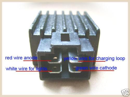
Red wire to positive, green wire to negative.
Chinese voltage regulator wired up to honda gx clone with charge coils. To read a wiring diagram, initially you have to recognize what basic aspects are consisted of in a wiring diagram, and which pictorial icons are made use of to represent them. 55w 4 wires, green= ground, red= power to the accessories/battery, pink and yellow = to the rotor/magento stator/generator It shows the components of the circuit as simplified shapes, and the capability and signal links together with the devices. Black to a switched live or just loop it back to the red. I double check the part number and it says 3 wire. Each component ought to be set and linked to different parts in particular manner. The 10 100 rectifier plugs into the harness at the same location as the oe rectifier. Referring the the ubiquitous 200 page service and repair manual that's floating around in pdf format, i went to page 156 (chapter 14: For example, on a 1981 kawasaki kz440, there are 5 wires going to the oe part: Trail tech stators have yellow lighting leads. 12 volt 4 pin regulator rectifier wiring diagram picture posted and published by admin that preserved in our collection. The battery kind of keeps a lid on it.
4 pin regulator rectifier wiring diagram. The rectifier outputs about dc14.5 voltage can charge for 12v lead acid battery and supply power for 12v bulb and so on. I show how to make connections for the headlight. As i mentioned in the last step, the different manufacturers tend to vary their wire colours so you'll need access to a wiring diagram for the make and model your regulator rectifier is off. Each part should be placed and linked to different parts in particular way.
110cc Kazuma Falcon Rectifier Atvconnection Com Atv Enthusiast Community from atvconnection.com When open open the engine cover, looks like the rectifier that already in there is a 4 wire square shape one. Chinese voltage regulator wired up to honda gx clone with charge coils. Voltage regulator 4 pin regulator rectifier wiring diagram from content.instructables.com print the cabling diagram off and use highlighters in order to trace the circuit. 1991 1999 kawasaki kle400 regulator rectifier 9899 1991 2003 kawasaki zx 600 ninja zx 6 d2 d4 regulator rectifier 11995 1991 2003 kawasaki zx7r ninja regulator repair kit 6499 1991. Wiring this regulator mini s pit bikes forum. Ok, i thought it is a 4 wire rectifier regulator, but six wire can be difficult to figure out. Simple harley wiring diagram wiring diagram data schema this article is made due to many queries after the post about deadbug prototyping so ive … To read a wiring diagram, initially you have to recognize what basic aspects are consisted of in a wiring diagram, and which pictorial icons are made use of to represent them.
When you make use of your finger or perhaps the actual circuit with your eyes, it's easy to mistrace the circuit.
I also show how to wire in a brake switch for the taillight. In this video, i show how to wire the rectifier/regulator to the stator of the pitbike. The rectifier comes with free wire adapter connect cable. Trail tech stators have yellow lighting leads. I show how to make connections for the headlight. If you are uncomfortable with reading a wiring diagram, scroll to the bottom and i'll tell you the wire colours for a honda one. Referring the the ubiquitous 200 page service and repair manual that's floating around in pdf format, i went to page 156 (chapter 14: 1991 1999 kawasaki kle400 regulator rectifier 9899 1991 2003 kawasaki zx 600 ninja zx 6 d2 d4 regulator rectifier 11995 1991 2003 kawasaki zx7r ninja regulator repair kit 6499 1991. 5 pin rectifier wiring diagram. › see more product details When open open the engine cover, looks like the rectifier that already in there is a 4 wire square shape one. With this kind of an illustrative guide, you are going to be capable of troubleshoot, stop, and total your projects with ease. If without 12v battery, the output voltage will be much higher.
If without 12v battery, the output voltage will be much higher. For example, on a 1981 kawasaki kz440 , there are 5 wires going to the oe part: Kawasaki voltage regulator wiring diagram. I ordered a rectifier received it and its a 3 wire rectifier. I double check the part number and it says 3 wire.
4 Wire Voltage Regulator Schematic 2011 Dodge 5500 Fuse Box Diagram Vww 69 Fordwire Warmi Fr from static-cdn.imageservice.cloud Wiring this regulator mini s pit bikes forum. Many rick's motorsport electrics rectifier/regulators eliminate what is commonly referred to as a signal wire on oe pieces. When you make use of your finger or perhaps the actual circuit with your eyes, it's easy to mistrace the circuit. If the module gets warm, you have connected it backwards. For example, on a 1981 kawasaki kz440, there are 5 wires going to the oe part: The battery and charging system) and found this diagram: How to wire a gm external regulated 10dn alternator. The 10 100 rectifier plugs into the harness at the same location as the oe rectifier.
12 volt 4 pin regulator rectifier wiring diagram picture posted and published by admin that preserved in our collection.
Many rick's motorsport electrics rectifier/regulators eliminate what is commonly referred to as a signal wire on original equipment (oe) pieces. When open open the engine cover, looks like the rectifier that already in there is a 4 wire square shape one. Simple harley wiring diagram wiring diagram data schema this article is made due to many queries after the post about deadbug prototyping so ive … If the module gets warm, you have connected it backwards. Yellow wire(s) to the alternator. Red wire to positive, green wire to negative. On a typical scooter with a 4 pin regulator such as the type being discussed, there is one incoming current, two outgoing positives and one ground. This regulator rectifier has to work together with a 12v battery. I also show how to wire in a brake switch for the taillight. 55w 4 wires, green= ground, red= power to the accessories/battery, pink and yellow = to the rotor/magento stator/generator As i mentioned in the last step, the different manufacturers tend to vary their wire colours so you'll need access to a wiring diagram for the make and model your regulator rectifier is off. 4 pin regulator rectifier wiring diagram. To read a wiring diagram, initially you have to recognize what basic aspects are consisted of in a wiring diagram, and which pictorial icons are made use of to represent them.